About SSHS Lab.
Members
- Professor
- Post-Doc. Researcher/Research Professor
- Ph.D. Students
- M.S. Students
- Alumni
- Lab Secretary
- Exchange Students and Undergraduates
Publications
- Publications
- International Journal
- International Conference
- Domestic Journal
- Domestic Conference
- Thesis and Dissertation
- Invited Lectures and Seminar
- Patent
- Honors and Awards
- Technical Notes
Research
- Research
- Shock & Vibration Control
- Space Structure
- AI-based Smart System
- Flapping Wing Air Vehicles
- Hardware we have developed
Projects
Lectures
KAIST-UVARC
Lab Blog
c. Shock Absorbing Structures
Shock & Vibration Control

 Research
Shock & Vibration Control
c. Shock Absorbing Structures
Research
Shock & Vibration Control
c. Shock Absorbing Structures
c. Shock Absorbing Structures
Principal Investigator: Jae-Hung Han (SSHS), Dae-Hyun Hwang (SSHS)
Participating Graduate Research Assistants: Hyun-Su Park (SSHS), Yong-Ha Hwang (SSHS)
Related Projects: 1) ADD/LIGNex1 (Finished), 2) ADD/한화
Summary:
Pyrotechnic fastener or Explosive Bolt uses explosive charges which can be initiated remotely to break the bolt into two pieces. It is incorporated mainly to application in military ordnance spacecraft, aircraft and underwater vehicle systems. Several applications like stage separation, escape tower release and landing systems would be impossible without them. However, most design processes of pyrotechnic fastener (explosive bolts) are relying on researchers’ experience and experiments which requires numerous cost and time. To remedy aforementioned problems, numerical analysis of separation behavior can be conducted prior to experiments. By utilize results of numerical analysis, designer can evaluate separation success rate without experiments and improve reliability of separation by design modification. Also, due to their high acceleration and high frequency, pyro-shocks can cause electronic hardware to fail leading to catastrophic failure. There are several examples of flight vehicles that have crashed after a routine explosive device deployment, where the cause being determined to be the result of electronic devices failure due to the explosion. Thus, it’s very important to anticipate the shock environment around the major hardware installation section. Also, pyroshock can be attenuated by newly developed three-axis hybrid mesh isolator using pseudoelasticity of a shape memory alloy. As a different approach to avoid explosion induced problems, low-shock separation devices have been developed. Especially the pressure cartridge actuator has very short operation time (within 1 ms) and generate high energy. Therefore, indirect evaluating methods based on experimental results are commonly used because the separation procedure time is too short to experimentally identify the behaviors of internal parts. Thus, to identify the separation procedure in detail, numerical analysis of mechanical behaviors of the Ball-type separation bolt is conducted using explicit analysis. Utilizing this explicit analysis method and the developed mathematical model, time and cost of development process can be reduced.Related Recent Publication:
- [1] Park, H.-S, Hwang, D.-H., and Han, J.-H., “Development of shock-absorbing insert for honeycomb sandwich panel”, Aerospace Science and Technology, Vol. 104, Article No. 105930, 2020.
- [2] Hwang, D.-H., Park, H.-S, and Han, J.-H., “Development of a miniature point source pyroshock simulator”, Journal of Sound and Vibration, Vol. 481, Article No. 115438, 2020.
- [3] Hwang, D.-H., Lee, J., Lee, Y., Kim, D., and Han, J.-H., ”Performance optimization of a split-type low-shock separation bolt”, Journal of Spacecraft and Rockets, Vol. 58, No. 1, pp. 232-239, 2021.
Shock propagation analysis on honeycomb sandwich panel structure
1.Goals
- Identify shock wave propagation characteristics on honeycomb structure with various joints.
2. Approaches
Conduct shock propagation experiment- Laser Doppler velocimetry (LDV) is used.
- Various joint such as corner joint, butt joint, T-shape joint is made.
- Shock Response Spectrum(SRS) is used to quantity magnitude of shock.
- Attenuation of shock can be identified by measuring before and after joint.
- ANSYS Workbench Explicit Dynamics and ANSYS AUTODYN are used
- Maximum mesh aspect ratio is considered to reduce the calculation time.
- Analytical results and experimental results are compared.
- The parametric study is conducted using finite element analysis method.
3. Research Achievements
Shock propagation experiment for Honeycomb & Plate joint structure was conducted.- Insert was installed on honeycomb sandwich panel.
- Honeycomb panel with insert and plate was bolted.
- Measuring before and after joint, attenuation factor of insert system was identified.
3. Recent Achievements
A new folding methodology for the Yoshimura cylinder is developed.- Much efficient (inducing less stress and requiring less force) folding methodology is developed for the Yoshimura cylinder.
- The effectiveness of the proposed folding methodology is confirmed through the static analysis using ANSYS.
- This folding methodology could be a foundation for the 3-D deployable structure with Yoshimura pattern.

Fig.1 Insert and Honeycomb & Plate Joint Structure
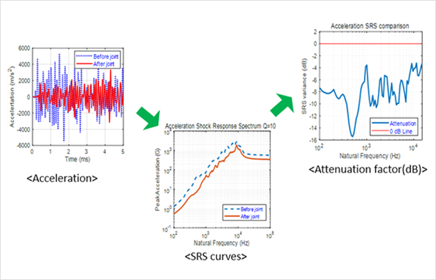
Fig.2 Experimental results (Acceleration, SRS curves, Attenuation factor)
- Analysis on honeycomb & plate joint structure was conducted.
- Analysis results are verified by comparing with experimental results.
- Parametric study can be conducted using verified analysis method.
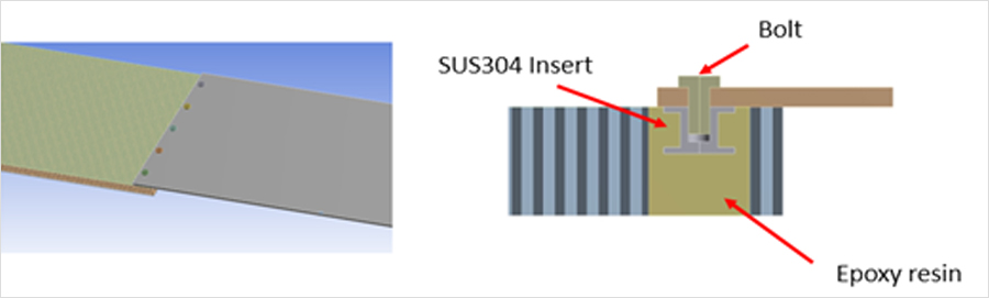
Fig.3 Modeling for finite element analysis
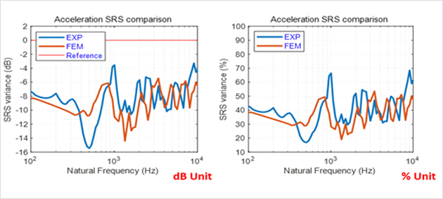
Fig.4 Comparing the attenuation factor of experimental and analytical results
Fig.5 Shock wave propagation
Separation Behavior Analysis and mathematical modeling of separation device using pressure cartridge
1.Goals
- Establishment of the mathematical model which can describe the dynamic separation mechanisms with low computational resources and short time.
- Identify the separation behaviors using numerical analysis method (ANSYS AUTODYN).
2. Approaches
Design consisting mechanisms mathematically- Separation procedure can be divided into several stages based on mechanical event sequence of components.
- Each stage is governed by different simultaneous differential equations containing equations of motion and combustion equations.
- Saint Robert’s Law is used as a combustion model of zirconium potassium perchlorate (ZPP) charge.
- Friction model, O-ring model, bolt deformation model is considered for accurate simulation.
- To simulate this mathematical model, the MATLAB function ODE45 is used for the calculation of simultaneous differential equations.
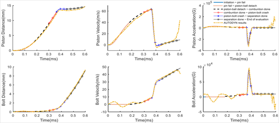
Fig.1 Time history of the mathematical model analysis for the movement of the components
- Design 3D model of the separation device by Solidworks.
- Export geometry to explicit analysis and generate mesh.
- Setup the boundary conditions for analysis.
- Simulate and identify the separation dynamics of the components.
Fig.2 Geometry and meshed model for explicit analysis of ball-type separation bolt
Fig.2 Geometry and meshed model for explicit analysis of ball-type separation bolt
- 3-D separation behavior analysis is performed
- Every contact condition is assumed to linear contact such as bonded or no separation
- Maximum mesh aspect ratio is considered to reduce the calculation time.
- Pretension load and deformation are applied by static structural analysis.
- Separation procedure is divided into five stages based on mechanical event of those parts.
- Each stage is governed by different simultaneous differential equations containing equations of motion and combustion equations.
- Saint Robert’s Law is applied as combustion model of ZPP propellant.
- To simulate this mathematical model, the MATLAB function ODE45 is used for the calculation of simultaneous differential equations.
3. Research Achievements
Sensitivity analysis using the established mathematical model- For several main design parameters, effects of each parameter on the separation performances are figured out in variance of ±20%.
- Validation by comparing the separation time with the experiment result.
- SEA is employed to analyze the propagated shock due to triggering of explosive bolt
- Detail separation procedure is identified from dynamic characteristics of internal parts.
- Parameter study on the coefficient of friction is conducted
- Analysis results are verified by comparing separation time with AUTODYN simulation results.
Fig.4 3D model of the ball-type separation bol
Fig.5 Piston distance history of mathematical model analysis
Separation Behavior Analysis of Ridge-Cut Explosive Bolts
1.Goals
- Separation behavior analysis of Ridge-Cut explosive bolts for evaluate separation success rate without experiments and improve reliability of separation by design modification.
- Complex separation phenomena and characteristics of Ridge-Cut explosive bolts are understood by using separation behavior analysis.
2. Approaches
Using ANSYS Workbench Explicit Dynamics and ANSYS AUTODYN- 2-D Axisymmetric behavior analyses are mainly performed.
- Each stage is governed by different simultaneous differential equations containing equations of motion and combustion equations.
- An explosive bolt body is modeled using 0.2 mm Lagrange elements, Shock Equation of States (EOS), Johnson-Cook Strength model, Principal Stress Failure model and Geometric Strain (Instantaneous) Erosion Model.
- Modeling of PETN and RDX is done using 0.1 mm Euler elements and JWL EOS.
- Air is modeled using 0.1 mm Euler elements and Ideal Gas EOS.
- Ridge-Cut Mechanism (also known as spalling) by which Ridge-Cut explosive bolts are separated can be observed in the analysis.
3. Recent Achievements
Separation behavior of explosive bolts can be modeled.- Validation by comparing with experiments.
- The best prediction of the experimental results is obtained when 2.8×10^6 kPa critical value of normal tensile stress is used.
- Ridge-Cut Mechanism is observed.
- Some design guidelines about fixtures are suggested.
- For more information, Refer Lee, J.-H., Han, J.-H., Lee, Y.-J., and Lee, H.-J., “Separation Characteristics Study of Ridge-Cut Explosive Bolts”, Aerospace Science and Technology, Vol. 39, pp. 153-168, Dec. 2014. [DOI].
Fig.1 Cross-sectional diagram of ridge-cut explosive bolts
Fig.2 Modeling of ridge-cut explosive bolts
Fig.3 Pressure contour at 0.0027 ms (without failure model)
Fig.4 Material Status at 0.005 ms
Pyro-shock Analysis on a Missile Body due to Explosive Bolt Separation
1.Goals
- Predict the response of the subsystem of missile subjected to high frequency load due to activation of explosive bolt for stage separation
- Study the effect of several assumed loss factor and contrast it with the experimental results
2. Approaches
Using Statistical Energy Analysis (SEA)- Define System (dividing into different subsystem, defining relationship between them)
- Evaluate parameters like loss factor, mode count etc.
- Calculate response (frequency band averaged FRF magnitude)
- Assume virtual modes in which synthesized FRF approximates the frequency band averaged FRF magnitude.
- Using synthesized FRF, calculate response in frequency domain.
- Inverse Fourier transform to get time signal
- Use the time signal to obtain SRS
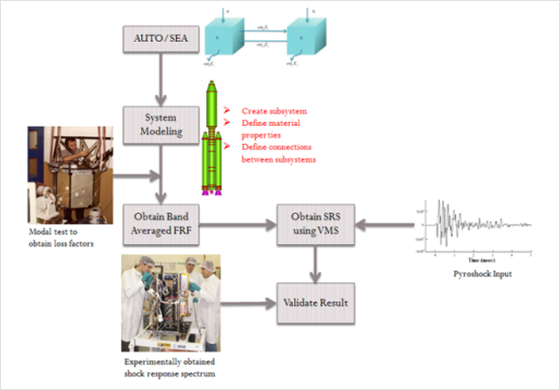
Fig. Auto-SEA/shock analysis methodology flow chart
3. Recent Achievements
High frequency shock propagation on satellite due to activation of explosive bolt is studied.- Behavior analysis of explosive bolt is performed using Ansys-Explicit Dynamics/AUTODYN
- SEA is employed to analyze the propagated shock due to triggering of explosive bolt
- For more information, Refer “Marshal Deep Kafle, Dae-Oen Lee, Juho Lee, Sung-Hyun Woo, Jae-Hung Han, “Numerical Modeling of Shock Generation and Propagation during Satellite Separation”, Advances in Aircraft and Spacecraft Science, Submitted.”
- Three plate connected in series is analyzed using EFM with built in MSC/Nastran solver
- SEA analysis is also performed and compared with EFM analysis
- For more information, Refer “Marshal Deep Kafle, Dae-Oen Lee, Sung-Hyun Woo, Jae-Hung Han, “Shock Response Estimation by Energy Flow Method and Virtual Mode Synthesis”, ICSV20, Bangkok, Thailand, July 7~11, 2013.”
- Missile body with 11 subsystems is modeled and the response is measured in each of them
- Several assumed loss factors are used to model the system and SEA predicted results are compared with the experimental results
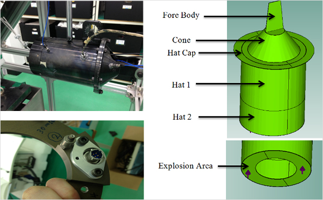
Fig. Experimental missile body (left) along with its SEA model (right)
Three-axis hybrid mesh isolator using pseudoelasticity of a shape memory alloy
1.Goals
- Develop a new three-axis hybrid mesh isolator using the pseudoelasticity of a shape memory alloy wire that was manufactured and tested to attenuate pyroshock and vibration transmitted to the electronic components.
2. Approaches
Manufacturing processes for three-axis hybrid mesh isolator.- Knitting : Manufacturing wire mesh using knitting machine with a continuous wire
- Cut & Fold over : Wire mesh is cut and folded over before inserting to the press machine
- Insert: Insert folded wire mesh to the designed press mold
- Pressing : Pressing folded wire mesh with a designed pressure
- Inspection
- To characterize the isolation capability, quasi-static loading tests were performed.
- The ground pyroshock tests are performed.
- Random vibration tests are performed.
- The healthiness of the hybrid mesh isolator was also studied.
3. Recent Achievements
A new three-axis hybrid mesh isolator is developed and performances are verified.- To characterize the isolation capability, quasi-static loading tests were performed; the test results showed that the pseudoelastic effect of the shape memory alloy wire significantly absorbs energy due to the stress-induced phase transformation.
- The ground pyroshock test results showed a remarkable pyroshock load attenuation of the hybrid mesh isolator in all frequency ranges.
- The dynamic characteristics and vibration isolation performances of the mesh isolators were also verified by random vibration tests.
- The healthiness of the hybrid mesh isolator was also studied under a harsh vibration loading level, and the results confirmed its wide applicability without degradation of the isolation capability.
- For more information, Refer “Youn, S.-H., Jang, Y.-S., and Han, J.-H., “Development of a three-axis hybrid mesh isolator using the pseudoelasticity of a shape memory alloy,” Smart Materials and Structures, Vol. 20, No. 7, pp.1-12, June, 2011.”
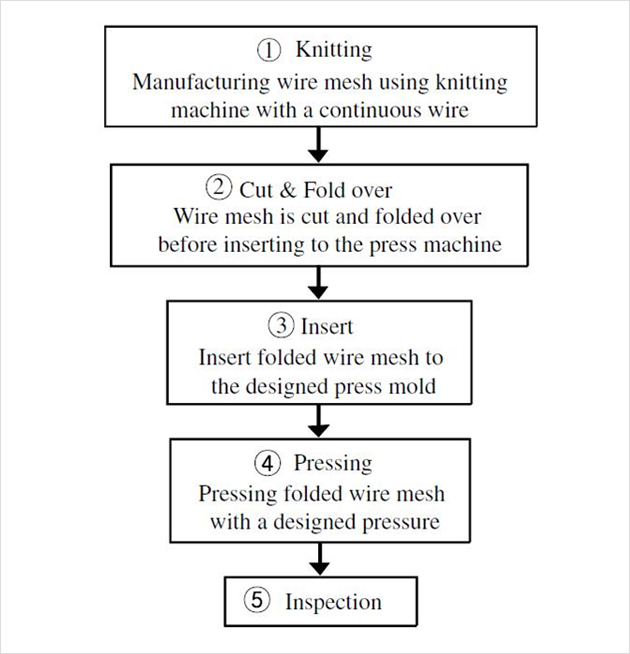
Fig.1 Manufacturing diagram of the mesh isolator
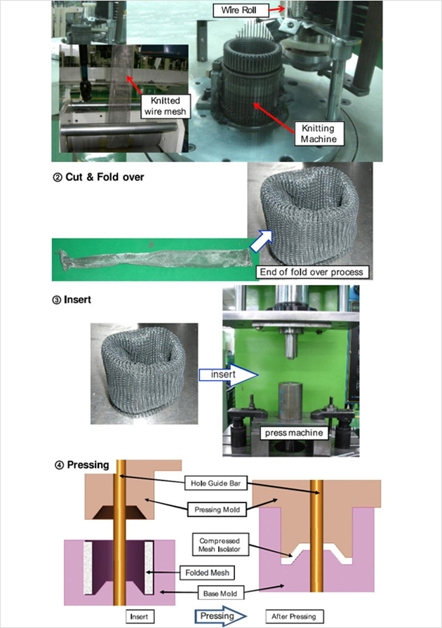
Fig.2 Manufacturing processes of the mesh isolators.
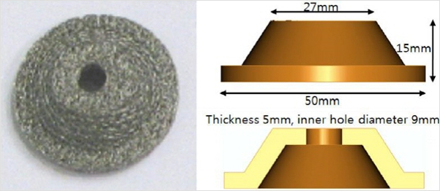
Fig.3 Manufactured and designed shape of the mesh isolator
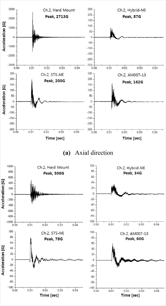
Fig.4 Comparison of the pyroshock test results in the time domain
Frequency tunable isolator based on shape memory alloy for effective shock and vibration suppression
1.Goals
- Develop a novel frequency tunable isolator based on shape memory alloy for effective shock and vibration suppression. If the natural frequency of the isolator can be controlled by changing the stiffness of the resilient material when an excitation frequency approaches the designed natural frequency of the isolator, the structural integrity can be ensured by preventing the amplification of the vibration.
2. Approaches
Manufacturing processes compressed mesh washer- Knitting : Manufacturing wire mesh using knitting machine with a continuous wire.
- Cut & Fold over : Wire mesh is cut and folded over before inserting to the press machine
- Insert: Insert folded wire mesh to the designed press mold
- Pressing : Pressing folded wire mesh with a designed pressure
- Inspection
- Bottom plate is connected with the vibration source.
- isolation materials are arranged between a vibrating source and an object.
- The SMA wire actuators connected between top and bottom plates and contracted at an Af -Austenite finish temperature.
- The recovery spring coiled around an outer of the isolation material.
- Natural frequencies test of the system with various compressive deformations.
- Random vibration tests are performed.
- WI Compressive load tests are performed.
- Phase transformation temperatures tests are performed.
- The tensile test at room temperature are performed.
- Recovery stress tests are performed.
- Frequency tuning testsare performed.
- Pyroshock tests are performed.
3. Recent Achievements
A novelfrequency tunable isolator is developed and performances are verified.- The compressed mesh washer isolator (WI) using the pseudoelasticity of the SMA was manufactured and tested: The stiffness change of WI can be easily achieved using a small compressive displacement.
- A concept of frequency tunable isolator was introduced: The resonant frequency of the proposed isolator is selectively controlled in two Modes. In Mode 1, the isolator has a lower natural frequency than in Mode 2. However, in Mode 2, the isolator has a higher natural frequency than in Mode 1.
- The frequency tunable shock isolator for launch vehicle was developed in order to achieve both shock attenuation performance and avoidance of the vibration amplification.
- The detailed design processwas introduced: The vibration characteristics of the WI and compressive load were observed through a random vibration test with compressive deformation.
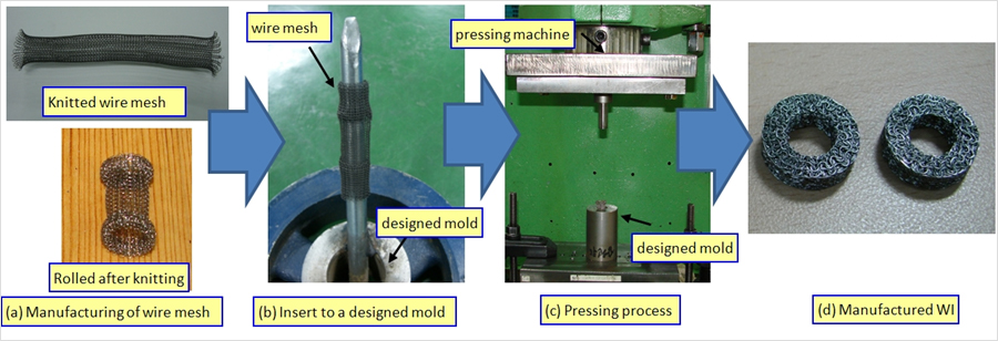
Fig 1.Manufacturing process of WI
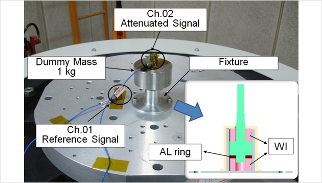
Fig 2.Test facilities for WI random vibration test
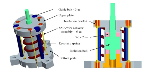
Fig 3.The mechanical model of proposed isolator.
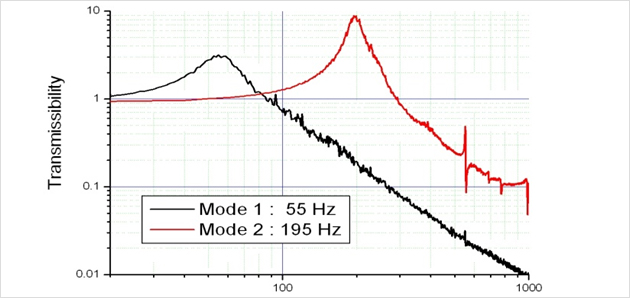
Fig 4. Transmissibility of the isolator with Modes.
COPYRIGHT BY Smart Structures & H/W Systems Lab. ALL RIGHTS RESERVED.